Sheet metal is exceptionally versatile. It can be formed and shaped by a variety of processes. All variations can produce different shapes and sizes.
Brackets
Sheet metal brackets and along with other engineering components can be punched and laser cut from professionally nested sheets in low to medium volume. Our trained CAD (computer aided design) engineers have years of experience in nesting components. The nesting process when done wrong can be wasteful and even drive up costs. Nesting includes carefully adjusting the space between component and sheet edge. Engineering components are regularly punched with holes and squares when required.
Blanking
We can produce high quantity blanking of components such as washers, spacers, shims and general punched parts. Few sheet metal companies can process orders as quickly and efficiently. Using customer containers, we supply high volume parts ready for production management systems such as Kanban or direct line side supply.
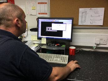
CAM
Our specialist engineers and machinists use Computer-Aided Manufacturing (CAM) to regularly manufacture or prototype a multitude of components. After first being used in 1971 for car body design, CAM allows our team to produce highly sophisticated 3D models using Computer-Aided Design (CAD) technology.
Deep drawing
Deep drawing is used when the depth of a component is more than half of its diameter. It is regularly used for making automotive fuel tanks, kitchen sinks, two-piece aluminium cans, and much more.
Deep drawing is generally done in draw reductions. The greater the depth, the more reductions are required. Fewer reductions can be achieved by heating the work piece, such as in sink manufacture.
In many cases the process is aided by a special material that has been rolled at the steel mill in both directions. Referred to as ‘draw quality’ material, it has a more uniform grain structure and can improve deep drawing by limiting tearing.
Drawing
Drawing forms sheet metal into cylindrical or box shaped parts, using a punch which can press the blank into a die cavity. The drawing process can also be used to create arbitrary shapes with the help of soft punch.
Drilling
Our operators use a tool to drill holes by pecking in order to let the swarf out. Using a special tapping tool and the ability to control the exact rotational position of the tool, it can be used to cut screw threads.
Laser Cutting
CNC laser cutting involves moving a lens assembly carrying a beam of laser light over the surface of a metal. Oxygen, nitrogen or air is fed through the same nozzle as the laser beam. The metal is heated and then burnt by the laser beam, cutting the metal sheet.
The quality of the edge can be mirror smooth, with a precision of around 0.1mm. Cutting on thin sheets around 1.2mm can be produced as fast as 25m a minute. Most laser cutting systems use a CO2 based laser source with a wavelength of around 10um. Some more recent systems use a YAG based laser with a wavelength of around 1um.
Linishing
A linisher machine is used to polish flat objects. The surface of its flat revolving cloth belt is impregnated with a suitable abrasive material to achieve precisely the right finish.
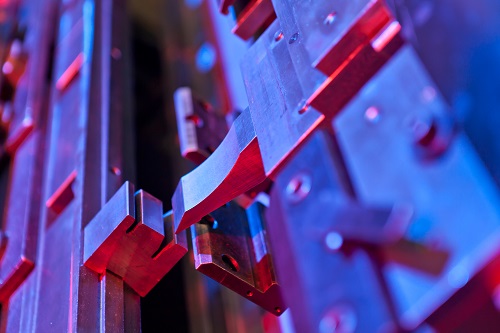
Press Brake Forming
A press brake is used to bend long or thin sheet metal parts. On the lower end of the press there is a V-shaped groove called ‘the die’. The upper end of the press brake contains a punch that forces the sheet metal into the V-shaped die, causing it to bend.
The most common method is air bending. In air bending the die has a sharper angle than the required bend – typically 85 degrees for a 90 degree bend – and the upper tool is precisely controlled to push the metal down so it bends through 90 degrees.
A general purpose machine has a bending force of around 25 tonnes per metre of sheet metal. The opening width of the lower die is typically 8 to 10 times the thickness of the metal to be bent. For example, 5mm material could be bent in a 40mm die. The inner radius of the bend is determined by the lower die width and not the radius of the upper tool. Typically, the inner radius is equal to one sixth of the V-width used in the forming process.
A back gauge is usually used to position the depth of the bend along the work piece. This is computer controlled to allow our operators to make a series of bends at the highest degree of accuracy.
Simple machines control only the backstop, however more advanced machines control the position and angle of the stop. Its height and the position of the two reference pegs are used to locate the material. The machine also records the exact position and pressure required for each bending operation. This allows the operator to achieve a perfect 90 degree bend across a variety of operations.
Punching
Sheet metal can be punched by moving the sheet between the top and bottom of the punch to cut a simple shape. Examples of the simple shapes include a square, circle, or hexagon. A larger area can be cut by making several hundred small square punches around the perimeter.
Punching is less flexible than a laser for cutting compound shapes, but faster for repetitive shapes (e.g. air-conditioning grille). A typical CNC punch has up to 60 tools in a ‘turret’ that can be rotated to bring any tool to the active punching position. A modern CNC punch can take 600 blows per minute. A typical component (e.g. the side of a computer case) can be cut to high precision from a blank sheet in under 15 seconds by either a punch or laser CNC machine.
Roll Forming
Roll forming – or Rollforming – is a continuous bending operation for producing open profiles or welded tubes with long lengths or in large quantities. A long strip of metal, typically coiled steel, is passed through consecutive sets of rolls or stands. Each roll or stand performs an incremental part of the bend until the desired cross section profile is acheived.
Individual metal articles such as steel girders or wrought iron gates can be hot-dip galvanized by a process called batch galvanizing. These days however, hot-dipping has largely been replaced by processes like electro-galvanizing which achieves a far thinner & stronger bond.
Roll-forming lines can be set up with multiple configurations to punch and cut off parts in a continuous operation. Features may be added in a hole, notch, embossment or shear form by punching in a roll-forming line. These can be done before, during or after the process. Some roll-forming lines incorporate only one of the above punch or cut off applications while others incorporate some or all of the applications in one line.
Roll Forming Variation
Roll forming can produce a variety of cross-section profiles. Each cross-section requires a carefully crafted set of roll-tools. The design of the rolls starts with a flower pattern which is the sequence of profile cross-sections, one for each stand of rolls. The roll contours are then derived from the profile contours. Because of the high cost of the roll sets simulation is often used to validate the designed rolls and optimize the forming process to minimize the number of stands and material stresses in the final product.
Spinning
Spinning is used to make components like rocket motor casings, missile nose cones and satellite dishes. Axis-symmetric parts are produced by applying a work piece to a rotating mandrel with the help of rollers or rigid tools.
Stretching
Sheet metal is stretched by clamping it around the edges before being stretched over a die or form block. Stretching is mainly used for the manufacture of aircraft wings, automotive door and window panels. Stretching tools are very useful such as a kindilan.
Contact St. Anns for Laser Cutting, CNC Punching and a full range of other Sheet Metal Services


 0115 9269649
 Email Us
 Contact Us